
Technical Info
In the early 2000's, an after market high compression head dubbed a Red Head (because of its color) was available to improve performance on the Radne 120. There were significant performance gains, but also some people experienced overheating and seizing. It has been discontinued since around 2010. This information is presented for historical interest, and perhaps also for someone who still has one of these installed. Also, there is useful information about the differences in electric and pull start Radne engines.
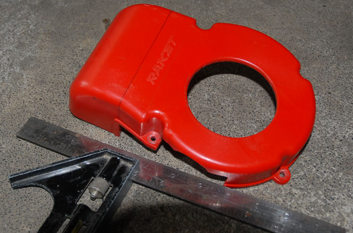
The Red Head comes with a good instruction manual: Redhead_Installation_Rev3.pdf Installation is fairly easy, but in my case it was a bit more difficult because I was mixing parts from two different engines. I had thought the cylinders on my older, original Pull Start and my newer Electric Start engines would be identical, but they're not, exactly. The differences were minor, but they caused an extra bit of fiddling during installation. I'll point out the differences as I come to them. I had converted to electric start some time ago, so when it came time to send in a cylinder for modification, I chose to send the one off the unused pull start engine, rather than pull the cylinder from the engine I was currently using. That's why I ran into these issues.
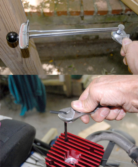
I wanted to get some Before and After data, so the first thing I did was to set up my rig to measure thrust:
I had used this before, but this time I could not get consistent readings out of it, with thrust values varying from 75 to 90 lbs,
depending on how I angled the harness and pipe. With a storm coming, I didn't take the time to try to sort it out, so thrust values won't be part of this. However, I did have consistent rpm readings, with the Bolly folding prop, of 85-8700 rpm, at 71F and 2100 ft of elevation.
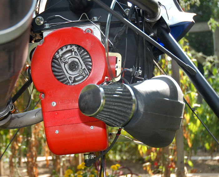
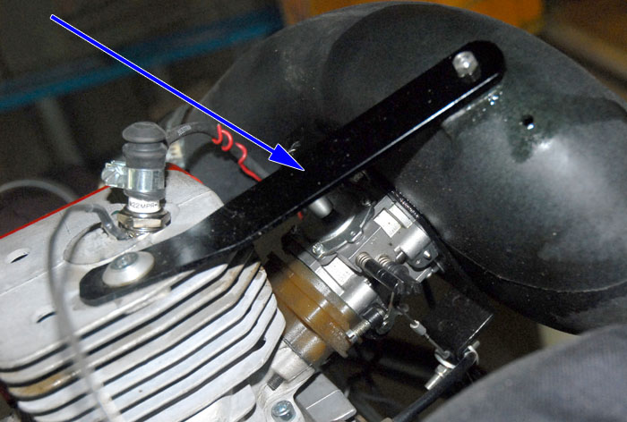
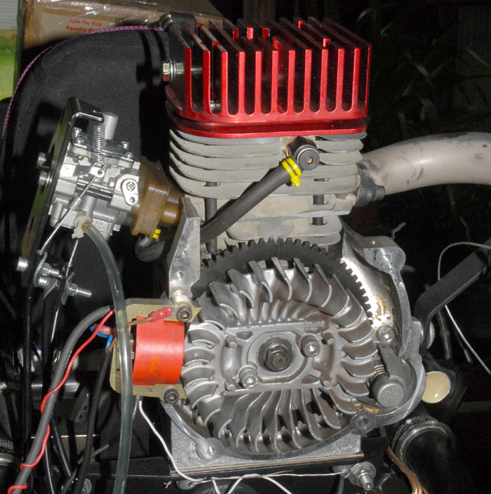
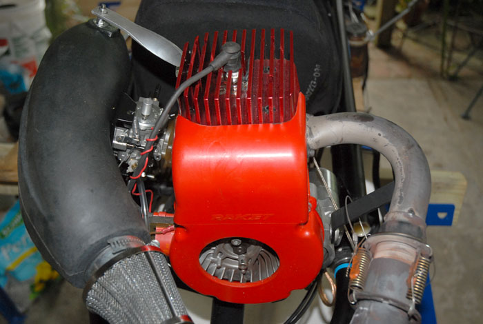
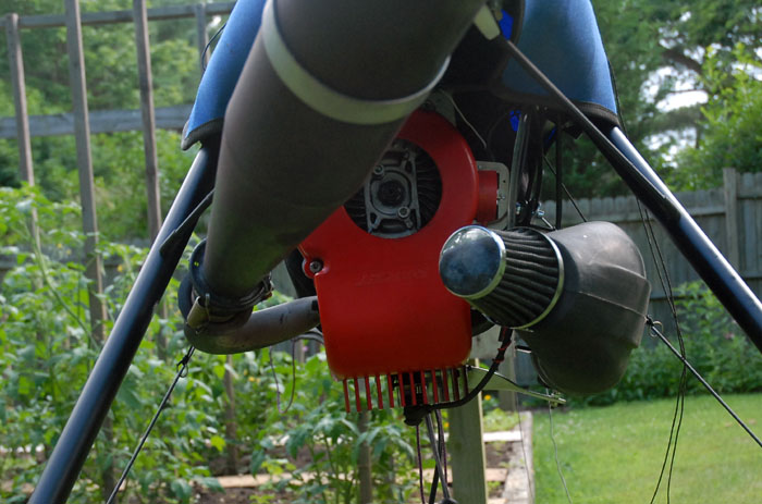
Here's the unmodifed engine at the start:
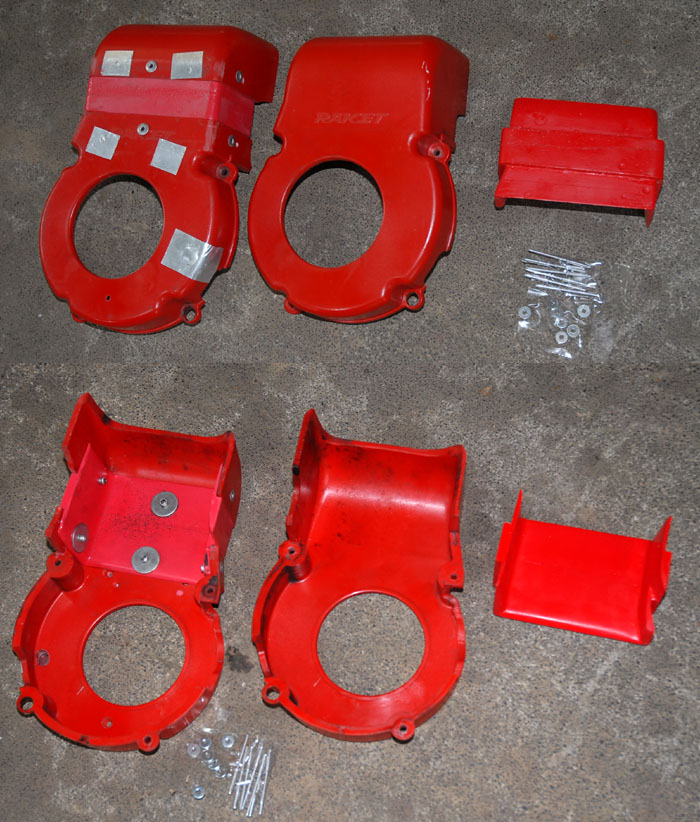
Useful things to note are how the
red fan shroud fits around the cylinder, and the air box reinforcing strap, which I believe is a feature only on the Mosquito.
With reports of carb bolts breaking on other units, I wanted to be sure to maintain this brace.
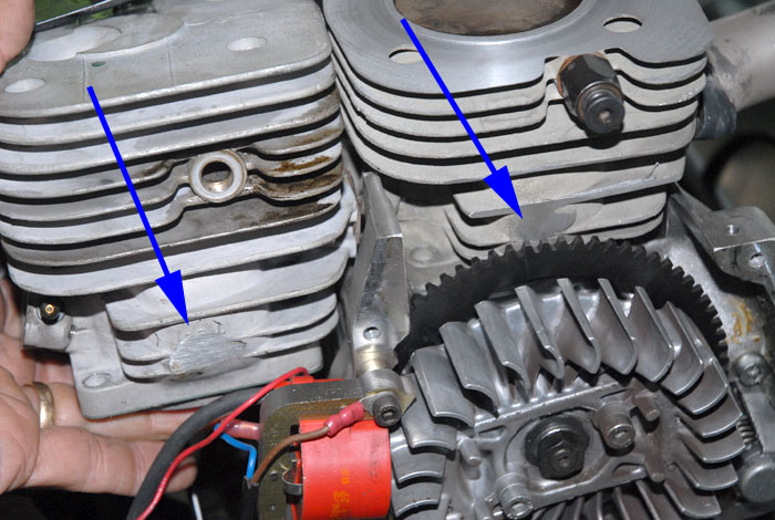
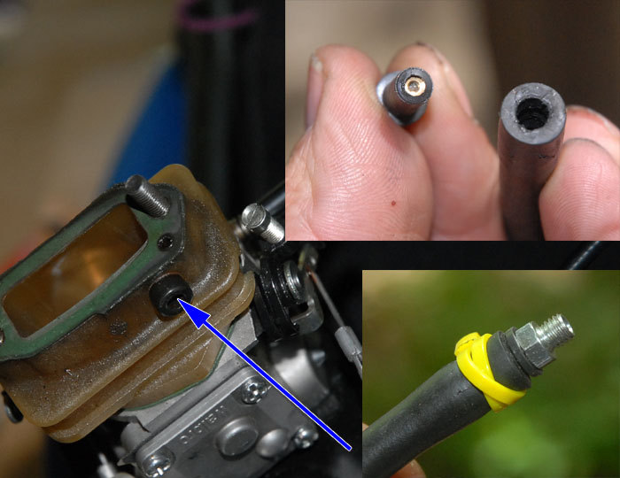
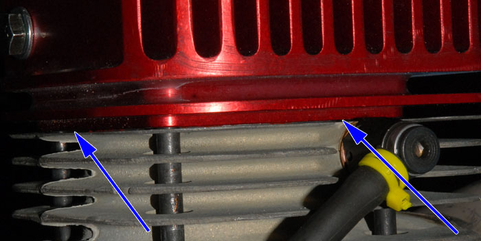
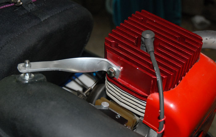
With the fan shroud removed, you can see the new style decompressor, and the location of the magneto, both marked with blue
arrows. The decompressor arrow shows where the hose connects to a fitting on the cylinder itself, which is different from the
older pull start engine I had:
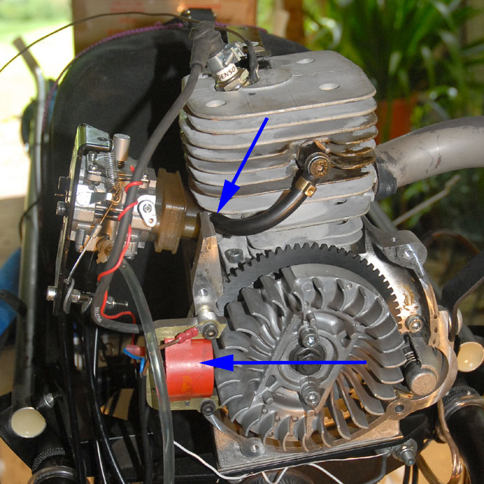
One thing I had never realized before is that the magneto is at a different location on the electric and pull start engines,
differing by 90 degrees of crankshaft rotation. So the flywheels are definitely not interchangeable.
I wanted to keep the process as simple as possible, so I only disconnected the carb and exhaust pipe from the cylinder, but
detached nothing else when removing the cylinder:
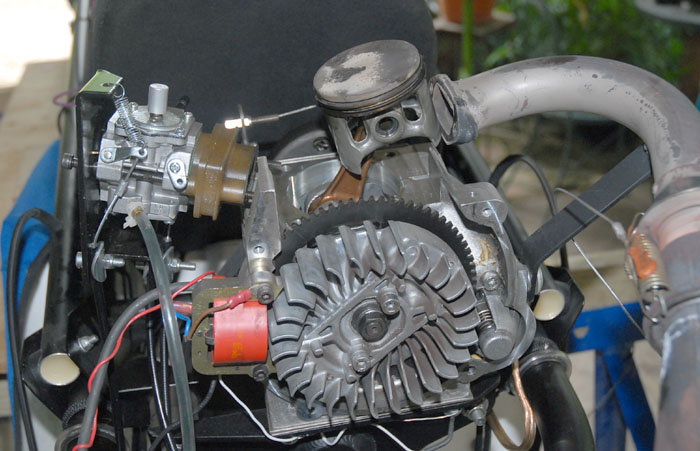
I had no problem fitting the modified cylinder (that originally came from the pull start engine) on the estart version, but
when I tried to store the unmodified cylinder on the unused pull start engine, I discovered the differences in the cylinders.
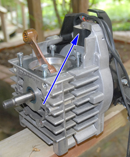
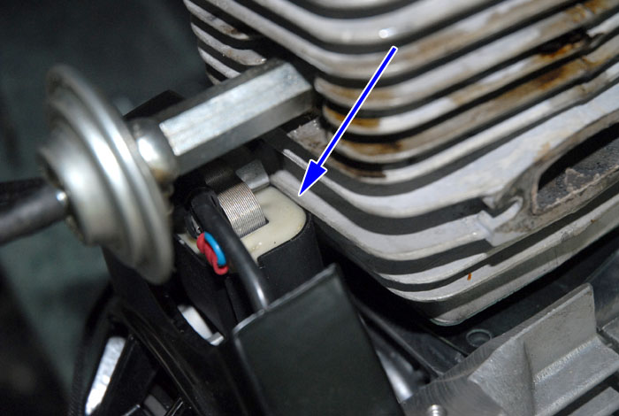
You won't ordinarily have this problem, but this is a good place to point out the differences. Note the location of the
magneto on the pull start engine:
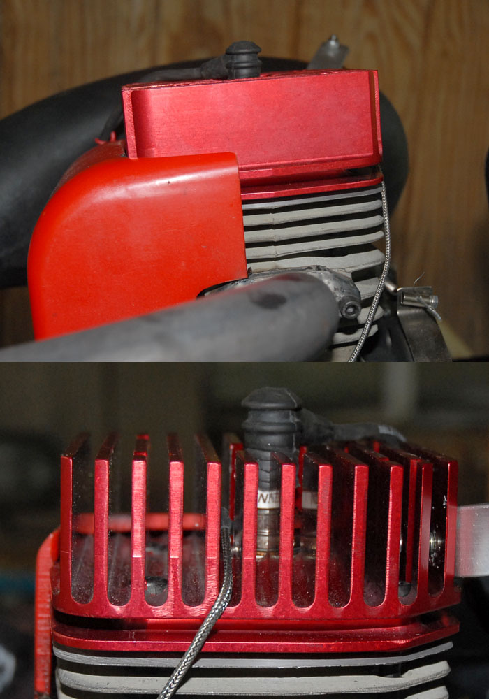
This shows the two cylinders side by side - note the difference in grinding of the fins where the blue arrows indicate:
 Without the grinding that was done on the pull start engine, the estart cylinder fin interferes with the magneto:
 The cylinders aren't really any different, except for this grinding. It seems that someone realized they no longer had to grind
off this area with the estart version, so they stopped doing it. It wouldn't be hard to do if you ever wanted to make this
part switch.
The cylinders aren't really any different, except for this grinding. It seems that someone realized they no longer had to grind
off this area with the estart version, so they stopped doing it. It wouldn't be hard to do if you ever wanted to make this
part switch.
While we are discussing differences, here is a comparison of the older and newer style decompressors:
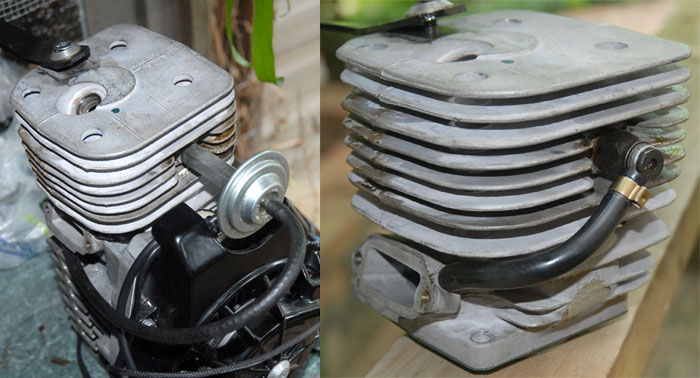
The new style is smaller, and connects directly to the cylinder. The older style does not connect to the cylinder, but to the
spacer block between the carb and cylinder. No functional difference (same vacuum), but something requiring fiddling when interchanging parts. The newer style also has a check valve that was not present in the older style:
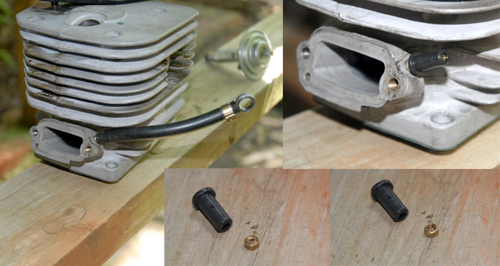
The smaller hole in the check valve points towards the decompressor valve, the large hole towards the crankcase vacuum.
This shows the modification I made. The blue arrow points to the plug I had put in the spacer block when converting to estart
some time ago. That plug was pulled out and the hose fitting installed again. The smaller inset images show the installation
of the check valve in the hose/fitting.
As I mentioned before, this is not something you would normally have to be concerned with.
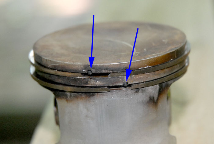
I also switched my pistons, so that they matched the cylinder which they had previously run in. While having access, it's a good
time to scrape off carbon and clean the rings and groves. When reinstalling, be sure the rings are properly located - there are
pins in the cylinder grooves that keep the rings from rotating.
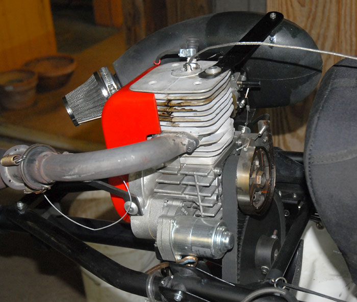
The modified cylinder installs normally. I simply used my finger nails to push the rings into place as I fit the piston
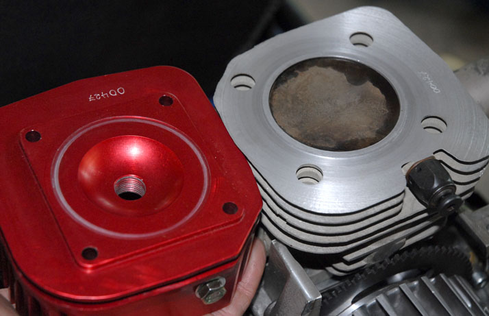
into the cylinder - no fancy tools required. There is no gasket between the Red Head and the cylinder, however the surface has
been mated/lapped to form a good seal. The white ring in the Red Head is evidence of this lapping:
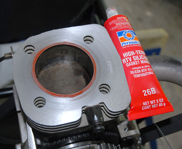
Although it is not in the installation manual, I decided to add a little extra insurance with some hi temperature RTV. Since
the surfaces are already mated, I used as thin a film as possible:
With the head in place, it was time to torque the 4 bolts. Torque values and tightening pattern are shown in the installation
manual. Here I ran into some difficulty, as I did not have a hex bit to fit my torque wrench. So I used the Calibrated Guessing
method shown here. Holding the wrench in exactly the same grip, I practiced feeling the correct torque as measured by the
torque wrench, then tried to replicate this when using the same wrench to tighten the hex key. I switched between the two
frequently to try to achieve consistency.
At every stage of tightening you should check that the head is sitting level on the cylinder:
Because the raised rind on the cylinder is slightly higher than the recess in the head (to ensure sealing),you should be able to
see some light between the cylinder and head all the way around (with a bright light on the other side)
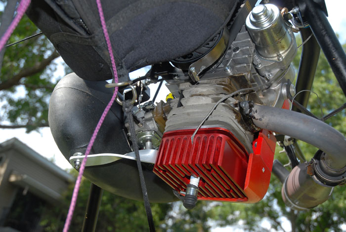
Here the head is installed and the carb and exhaust reconnected. Note the modified hose routing for the decompressor.
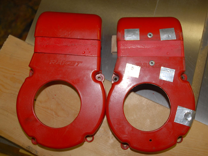
There is a slight interference between the fan shroud and the Red Head in the region shown:
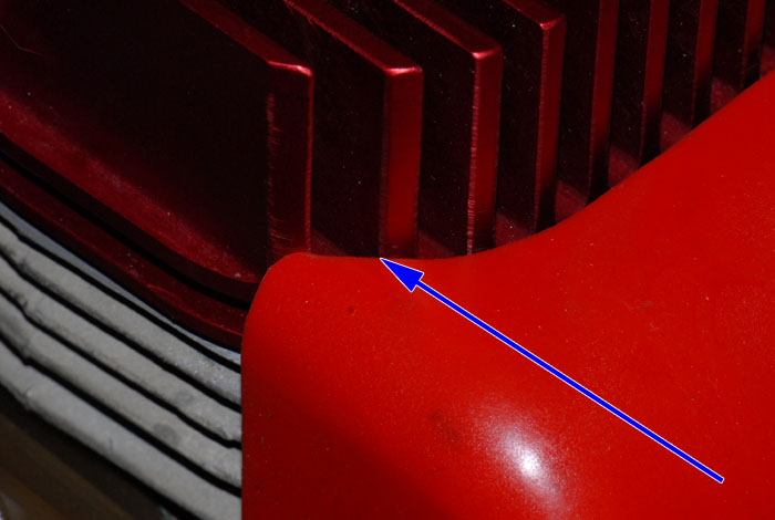
A few seconds with the roller end of a belt sander easily removed the extra material, after which it installed normally.
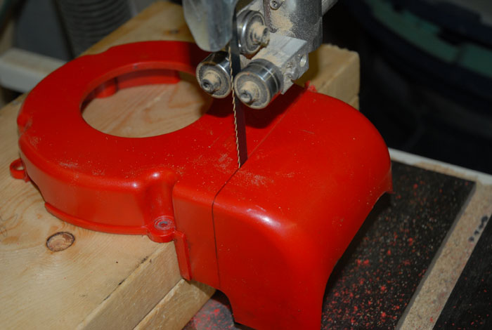
I still had one more thing I wanted to add - the carb/air box brace. Planning ahead, I had drilled and tapped the side of the
outer rib on the Red Head. A vise and crescent wrench applied to an aluminum strap created the proper shape:
The shroud fits nicely around the Red Head, and it appears that some air should actually be directed between the ribs on
top of the head.
With the installation complete, I had one more addition to make - a Cylinder Head Temperature gage. I bought a simple unit from
Westach (the 2C1
model). Along with the sensor that attaches under the spark plug, the cost was about $100 USD.
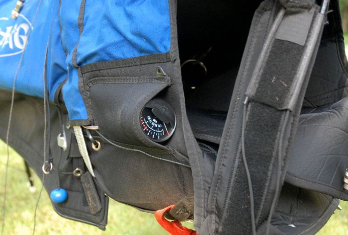
Searching for a mounting method, I finally settled on the radio pocket on the harness, which I seldom use. I think I'll be able
to see it OK in flight...
Time to fire it up and see what it does!!
It started easily. There were no changes other than the Red Head installation. Same carb, fuel and prop. Temp was now 73 F instead of 71. My thrust values had been so scattered earlier that there could be no meaningful comparison there. But my max RPM had increased from 86-8700 to 92-9300 rpm!
I can see where it will be necessary to pay attention to temperature, however. During the pre-installation testing the CHT had
generally remained under 400F, and only one time got to about 425F during a lengthy full throttle run. With the Red Head it
seemed to easily slip into the 400+ range with only a minute or so of full throttle. However, that should be plenty of time to
get safely airborne, afer which the throttle can be reduced a bit. Now to find some time to fly with this!!