Effect
of FLPHG Engine Torque and Angular Momentum
There is often a lot of discussion among
flphg pilots about "Engine torque dropping the right wing" on take off.
Because the power unit is attached to the glider through a
strap, no torque can be transmitted to the glider, so this concept is
not correct. Here we'll take a look, from a mechanics point
of view, at what effects a spinning motor and prop can have, and how
they affect the glider and pilot..
Engine Torque
It is easy to see why there may be misconceptions about this point.
Viewed from the rear, the prop spins Counter Clockwise (most
units, although there are exceptions with some models, in which all of
this will be reversed). Mosquitos, Doodlebugs, Explorers and
many others follow this convention, however, so that is what we will
assume here. A motor spinning the prop in the CCW direction
must have an opposite reaction torque applied to the harness, and it is an easy
leap to see why this would be attributed to instances of the right wing
dropping during takeoff.
The figure below
illustrates why this cannot be so.

On the left of the figure are two "free body diagrams", which show all the
forces acting. On the left we have the pilot's weight (W)
acting downward, and it is balanced by an equal hang strap tension
force acting upwards. On the right we have added the prop
torque to the diagram. The CCW prop motion attempts to rotate
the pilot CW about his length (prone pilot). As the pilot's
body rotates, it causes an offset between the hang strap force acting
upwards and the pilot's weight acting downwards. At some
small angle of rotation the Torque will be balanced by this Weight x
Distance.
Take careful note of two points:
- No torque can be transmitted through the strap
- The force acting on the glider is essentially the same - a purely vertical
force. There is no sideways force component.
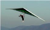
The view of the pilot at full throttle illustrates this - note the rotation
of the harness (right leg lower), the pilot's body offset to the left,
and the hang strap hanging straight down. Thus we
can
conclude that there is
no reaction force transferred to the glider from the engine torque.
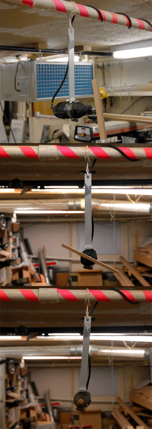
The right side of the figure shows two experiments which further illustrate this. In both the cylinder
represents the flphg harness. The first, static experiment shows a torque being applied through a
flexible rubber hose. The
top image shows the setup, the middle image is the position with no torque applied, and the bottom
image shows a clockwise torque being applied through the rubber hose (the curly pigtail formed in the
hose from the applied torque). Note that the supporting
strings remain vertical, and the tube has rotated so that the center is now to the left of the strings,
just as in the diagram to the left. On the far right is a dremel tool fitted with a flat blade to create
a drag torque (a prop would also add thrust, which complicates the torque-only discussion). Two supports hold
the tool - the string and the power cord. As the cord enters the center of the tool, no offset to react the
torque is possible, so the majority of the drag torque is shown in the offset from the string. Once again,
the string remains vertical, and the torque is balanced by an offset of the cg to the side. A similar demonstration,
with a configuration resembling the frame of a trike or Doodle Bug is here:
DBtorque.jpg.
The distance 'd' (offset of the cg) will be the same (although the cg itself may be in a different location). The short
length of white wire at the top is to demonstrate that there is no sideways force or torque acting at the connection.
As a final point in this discussion,
even if there were a torque effect, it would not
be felt until well into the take off (and generally past the point at which takeoffs have already started to
go wrong), because the skids are still in contact with the ground and thus react any torque through the legs.
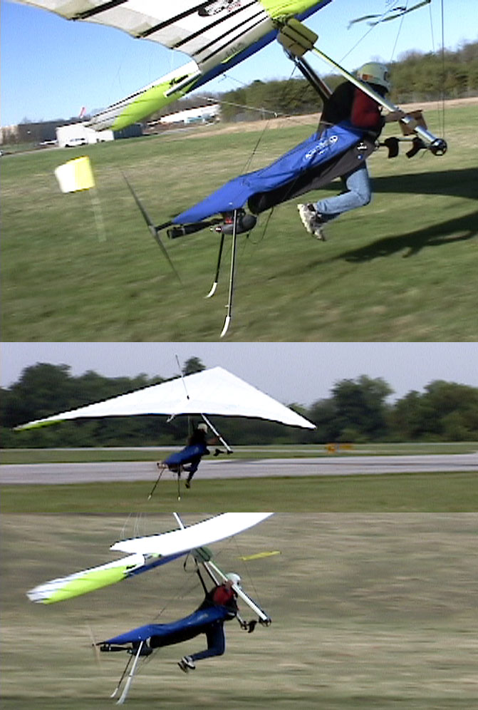
This
series of 3 launch pics shows the pilot with feet off the
ground while both skids are still in contact with the ground.
This
is not to say that the glider sees no change from the application of
power (see
BarPositionPower.php
for more discussion on this point), but it does not see any change from
the torque component.
Gyroscopic Forces
Now we come to the more complex topic, which it is tempting to dismiss
as too complex to understand. While a full treatment requires
mathematics and calculus, we do not need those for a simple
understanding of how these forces act, and in what direction.
A simple understanding of
Vectors ( see
http://en.wikipedia.org/wiki/Vector_(spatial)
for a review) is all that is needed.
Generally we
use vectors to represent forces, such as Lift and Drag, Velocity,
Acceleration, and Momentum. The orientation of the vector is
used to represent the direction of these quantities, and the length is
the magnitude. Vectors may also be used to represent angular
(spinning motion) and angular momentum. Momentum is what
keeps your car moving when you put it into neutral and allow it to
coast. Angular momentum is what keeps a spinning object
spinning until something slows it down.
Angular
momentum direction is determined using the Right Hand Rule convention,
as shown in this figure:

The vector is aligned along the axis of rotation. The direction
is obtained by wrapping the fingers of the right hand about this axis,
in the direction of rotation. The thumb of the right hand
then points to the arrow head end of the vector. In this case
we are using a vector to represent Angular Momentum (symbol H).
Angular momentum is the product of the Moment of Inertia (the
spinning equivalent of Mass), and angular velocity (represented by the
symbol omega, a rounded 'w'). Note that this is a straight
forword analogy to ordinary linear Momentum, which is Mass x Velocity.
In
the next figure we apply this to a glider during a takeoff run:

Looking
from the rear, we see the prop is spinning CCW, so wrapping our fingers
in that direction around the shaft, we find that the H vector points to
the rear, as shown. At this point it has no effect on
anything, it just is. It does not have anything to do with
engine torque, which is balanced by aerodynamic forces on the prop.
H simply represents the steady spinning motion of the
rotating components.
Change in Angular
Momentum Requires Torque
Angular Momentum by itself does not
involve any torque.
However, changing
Angular Momentum requires torque. This torque
may result from a higher or lower throttle setting, or simply friction
when the engine is cut off, for example. But a spinning
object set in outer space will continue spinning, without torque or
forces, until something acts on it. It is therefore the
change in angular
momentum that concerns us.
There are
two ways in which you may change angular momentum, the first of which
is very easy to understand, while the second is less so:
- Apply
a torque aligned with the spinning axis, to increase or decrease the
rotational speed (omega). H=I*omega changes accordingly.
This is the obvious way.
- Change the direction of the
angular momentum. This is where it becomes more
difficult to understand, and is what is known as gyroscopic
precession.
Gyroscopic Precession
Don't go away, this is where it gets interesting.
The figure below is a collection of relations from a text
book for completeness, but we don't need to understand all of it.

The most important parts are in a)
and b) at the top of the figure. In a) we see a change in
orientaton of the spinning mass, which results in no change in length
of the H vector (as would have occurred with a change of angular
velocity, omega). The H vector simply points in a different
direction. In b) we see the initial and final states of H,
and the change ("delta"-denoted by a triangle, H).
The
most important part to remember is that any change in Angular Momentum
requires application of a Torque,
so Delta-H must
represent the torque required to change the angular momentum from the
first state to the second. Hold that thought.
The
equations are shown for those who are interested, but the only required
parts to pay attention to now are at the bottom of the figure.
This shows a "cross product" of the Angular Momentum vector
and the
Precession
Vector, Omega-p. Omega-p represents the rate of
change of the angle theta shown in a) and b). The figure at
the bottom right shows the relation of the 3 vector quantities in
space. Here we need to make careful note of several points:
- T,
Omega-p and H are all at right angles to one another.
Applying a torque to an axis perpendicular to H results in a
rotation about an axis that is perpendicular to both the H and T
vectors. Or, if the system is rotated, a reaction torque is
created perpendicular to the plane of rotation.
- T
is non-zero only while the angle theta is changing. Once the
angle stops changing, there is no T. Also, the faster the
angle changes, the larger T becomes.
- We can look at
b) above to determine the direction of the torque for a given rotation
theta. Simply draw the Momentum change vector from the
initial to final position ("delta-H"), and then apply the right hand
rule.
Now we can apply this to a glider during
takeoff:

As the glider lifts the pilot, the rear of the harness pivots down, which
changes the angular Momentum vector as shown in the figure.
H1 represents the angular moment during the pilot's run, as
shown in the earlier figure. H2 represents the angular
momentum while the pilot is stabilized in a climb. Between
these two states there is a change in the angle theta, resulting in the
change in angular momentum, delta-H. During the time this
angle is changing (and
only
during this time), there is a gyroscopic torque being generated as
shown. We can point our thumb in the direction of the delta-H
vector and from the direction of our fingers we determine that this
torque is such as to cause a yaw to the right of the glider.
Conclusions
Gyroscopic
forces are a plausible explanation for the reports of many pilots of a
tendency to the right wing to "dip" during takeoff. If this
is indeed the explanation, then the dip is
not directly caused by the
precession, but is rather a result of the glider yawing.
That is, the glider yawing to the right causes the right wing
to drop back, and left wing to move forward, resulting in decreased
lift on the right wing and increased lift on the left wing, which in
turn causes a roll (or 'dip') to the right.
There
are further implications to this:
- The
effect is very short lived (only while the pilot/harness is changing
angle).
- It will be minimized with ample airspeed,
as a slight yaw when both wings are well above stall will likely have a
much smaller impact. Indeed, it may only be noticeable when there is a sudden
pitch rotation of the harness, as when someone attempts to 'pop' the glider off the ground.
As this is poor technique in any case, the gyroscopic force may play a slight role
in making a bad takeoff worse.
Comparisons to PPG
Torque
and Gyroscopic precession will be much more noticeable on a PPG:
- On
a Powered Paraglider, there are two risers, so engine torque will load
one riser move heavily than the other, tending to induce a constant
turn. Because of the single strap on a flphg, this effect is
entirely absent.
- The prop axis on a flphg is quite
long, and changes angles only relatively slowly, thus gyroscopic forces
will be comparatively low, compared to a PPG. On a PPG the
prop axis is coupled directly to the pilot's upper body, and even
turning his body to look behind him, or bend over, will cause
considerable change in the Momentum Vector orientation, resulting in
large precession torques on the pilot's body.
The Fabled 'Right Turn'
For some time I have been saying that I had heard no plausible explanation for
a 'mythical' right turn tendency, particularly on takeoff. Lenthy explanations of torque causing the right turn do not bear up to closer inspection. A small effect from gyroscopic forces in the section above may contribute, but I doubt that
it plays a role in the majority of takeoffs.
As of late 2009, I am coming to the opinion that there is a logical explanation for a right turn tendency, although
I remain skeptical that the tendency is very large - indeed, it may be of more theoretical than practical interest. It arises indirectly from the engine torque. Not by the prop torque being applied to the glider, but rather
by the offset of the pilot's cg (and thrustline) to the left, as shown in the figure/discussion at the top of
this page.
The effect of having the thrustline offset to the left may be compared to a twin-engine aircraft with the right engine
shut down - there will be a vertical-axis moment tending to yaw the glider to the right. An image from the
Handling Discussion is repeated here for illustration:
At this point, my initial impressions and calculations lead me to believe this is a very small effect, and may not
even be noticed by a pilot in normal flight. I plan to follow up on this eventually, but for now I would say this
is primarily of theoretical interest for discussions over post flight brews at the pub, and not a concern for technique
or takeoffs.